This document describes extending the RM mobile device management with custom types of OMA DM client devices.
Defining a Custom Device Type
Each device in RM is uniquely identified by its type and ID, which are available as type and ID of the device root control unit of the corresponding device. The ID of OMA DM devices is obtained from the DevInfo OMA DM standard object ./DevInfo/DevId.
The type of the device is determined by a set of rules defined in OMD DM device definition files in XML format. Each device definition file corresponds to one class of devices and contains the conditions, which a device has to satisfy in order to be classified as belonging to this device class. Such a condition is expressed as a pattern, which is matched against the DMT structure of the OMA DM device. A single device might match the pattern of more than one device definition file. In this case, the device type is determined by the device definition, which declares the highest "ranking" attribute. The ranking attribute allows defining hierarchies of device classes – more generic device types (which define weaker DMT pattern conditions and having lower ranking) and more concrete device types (defining additional DMT conditions over the genetic type conditions and having higher ranking).
Device definition files are placed in the syncml/dev directory of RM and should be named after the device type they are describing (i.e. <device_type>.xml).
Device Definition File DTD
Following are the elements of the device definition file format and their semantics, described in a DTD-like manner.
XML Element Definition | Description |
|---|---|
<!ELEMENT device-definition (device-type, device-rank, device-filter?, dmt-filter*)> | Contains the definition of a single OMA DM device type and the conditions which devices have to match in order to be classified as belonging to this type. |
<!ELEMENT device-type (#PCDATA)> | Specifies the type of the OMA DM devices defined by this device definition file. |
<!ELEMENT device-rank (#PCDATA)> | Contains an integer number specifying the rank of this device definition file. The rank is considered when a single device matches more than one device definition files. In this case, the device type with higher rank number has priority. |
<!ELEMENT device-filter (#PCDATA)> | Contains a simple condition on the elements of the DevInfo standard OMA DM object in LDAP filter syntax. The properties which can be used in the LDAP expression are Man, Mod, DmV, Lang, DevTyp, OEM, FwV, SwV, HwV. |
<!ELEMENT dmt-filter (path-pattern, pattern-condition*)> | Specifies a condition over the DMT structure (DMT node existence or absence), in particular attributes and values of one or more DMT nodes retrieved from the device. The interpretation of this element produces a boolean output indicating whether the DMT structure of the device matches the filter or not. The device definition file may contain zero or more such elements. If there are more than one DMT filter and/or a device filter (described above), then they must all be matched in order to succeed the matching of the device-definition as a whole. If there are no <dmt-filter> and <device-filter> elements, then the device definition is considered applicable for any OMA DM device. For example, the device definition of the "Generic OMA DM Device" (mprm.generic.oma-dm.device) device type does not declare neither <dmt-filter> nor <device-filer>, therefore ensuring that each OMA DM device will be classified at least as "Generic OMA DM Device", even if it does not match any of the more concrete device types (defined with higher rank attribute). The positive <dmt-filter> (with attribute positive="true") is considered as matching when there is at least one node in the device DMT, which matches the pattern defined in the <path-pattern> element and satisfying the conditions defined in the additional <pattern-condition> elements. Respectively, the negative <dmt-filter> (with attribute positive="false") is considered as matching, if there is no node which matches the <path-pattern> and corresponding <pattern-condition> elements. |
<!ATTLIST dmt-filter positive (true|false) "true"> | Specifies if the <dmt-filter> must match or not match in order to have successful device matching, i.e. allows specifying a negative filter (logical NOT). Allowed values are "true" or "false". The default value is "true". |
<!ELEMENT path-pattern (#PCDATA)> | Contains a DMT path (URI), which is matched against the DMT structure of the device. The path pattern can be either a concrete fixed string (denoting the absolute URI of the node) or may contain one or more variables enclosed in {}. For example, ./DMAcc/AppAddr/{Name}/Addr is a valid path pattern containing one variable called {Name}. The path pattern is resolved by searching the DMT of the device for at least one node, which matches this pattern. For example if the device has a node called ./DMAcc/AppAddr/Default/Addr, then it will match the defined pattern and the variable {Name} will be substituted with the "Default" node on the device. Example: The following XML fragment illustrates a DMT filer used to determine if one device is an OSGi Handset, assuming that each OSGi Handset must have an interior node with the ./OSGi URI. <control-unit> <dmt-node> <path-pattern>{X}<path-pattern> <pattern-condition> <node-attr atrr-name="type">{X}</node-attr> <value>org.openmobilealliance/1.0/w7</value> </pattern-condition> </dmt-node> . . .</control-unit> In this example the <path-pattern>./OSGi</path-pattern> element specifies that a device must have a node with the ./OSGi URI, while the additional condition defined with <pattern-condition positive="true">...</pattern-condition> states that this node must be an interior node, i.e. its "format" attribute must be equal to "node". |
<!ATTLIST path-pattern try-struct (true|false) "false"> | Indicates if a whole tree structure should be requested from the OMA DM device while interpreting the filter. If this attribute has value "false", the information will be retrieved node by node. If the support for "Struct GET" command is off (set via an inheritable property), this attribute will be ignored. |
<!ELEMENT pattern-condition (node-attr, value)> | Defines additional constraints over the nodes compared with the matching pattern specified in <path-pattern> element. These additional constraints are expressed as a set of conditions over the values of DMT nodes and/or their node attributes (type, format, etc.). The nodes included in the conditions MAY be specified by using the variables included in the <path-pattern> element, whose concrete values are assigned during the pattern matching process. |
<!ATTLIST pattern-condition positive (true|false) "true"> | Has similar meaning to the positive attribute in <dmt-filter>. |
<!ELEMENT node-attr (#PCDATA)> | Specifies the value of a DMT node or of one of its attributes (type, name, format, etc). The target node is represented by URI. |
<!ATTLIST node-attr attr-name CDATA #REQUIRED> | Required. Specifies which node attribute is involved in the matching. Allowed values are "value", "type", "format", "name", "uri", "ACL" and "title". |
<!ELEMENT value (#PCDATA)> | Specifies the value used for evaluation of the pattern condition. |
Control Unit to DMT Mapping
An arbitrary class of devices, including any OMA DM enabled device, can be represented in RM by using the control unit model and therefore can be managed in a unified way. To represent a device as a set of control units, there should be one or more Control Unit Providers, which will represent the specific devices as hierarchies of control unit objects.
The RM offers enhanced mapping between the data models of OMA DM and RM, i.e. between DMT and control unit models respectively. In this case, you do not have to implement any Control Unit Providers, but only write:
Control Unit to DMT Mapping (CU-DMTM) files, which specify the exact mapping between concrete DMT nodes and control units representing devices of the specific type in RM.
CU-DMTM files are located in the syncml/dmtm directory of RM and their names should start with the device type they are related to. In particular, the naming convention of mapping files is <device_type>_<dmt_node_keyword>.xml, e.g. mprm.generic.oma-dm.device_Acc-1.2.xml.
Control Unit Metadata XML files, which define the control unit interface of the CUs representing the specific type of devices in the RM.
For every such CU-DMTM definition, there MUST be a corresponding control unit metatype (defined in a metadata XML), which defines the interface of the control unit type - number and type of the state variables and actions, parent relations, etc. Therefore, a CU-DMTM definition does not have to describe the control units completely – it only provides complementary information to that included in the CU metatype, which is related to the "implementation" of the control units of that type on top of DMT operations. See the Generic Device Management documentation for more information on control unit metadata.
The CU metadata XML files for the control units defined in the CU-DMTM files are located in syncml/cu directory and should be named after the control unit type.
The RM will automatically register Control Unit Providers for the control units involved in DMT-to-CU mapping.
CU-DMTM DTD
XML Element Definition | Description |
|---|---|
<!ELEMENT control-unit-dmtm (device-type, device-filter?, control-unit+)> | Contains one or more definitions of control units mapped to the DMT of a particular type of devices. |
<!ELEMENT device-type (#PCDATA)> | Specifies the type of OMA DM devices, which this CU-DMTM file is applicable for. Must match with the type specified in the device root CU metadata. If this element is empty, the control unit mapping defined in this CU-DMTM applies to all OMA DM devices (for example, standard OMA DM object definitions). |
<!ELEMENT device-filter (#PCDATA)> | Specifies additional constraints over the devices, which this CU-DMTM applies for. These constraints are defined in the form of an LDAP filter, containing an expression over the properties of the DevInfo standard object - Man, Mod, DmV, Lang, DevTyp, OEM, FwV, SwV, and HwV. |
<!ELEMENT control-unit (dmt-node?, cu-type?, cu-id?, cu-parent*, state-var*, action*)> | Contains the definition of a control type on top of a DMT sub-tree structure. For every such CU-DMTM definition, there MUST be a corresponding control unit metadata definition, which defines the interface of the control unit type (number and type of the state variables and actions, parent relations, etc). |
<!ELEMENT dmt-node (path-pattern, pattern-condition*)> | Specifies the scope of the control unit in the DM tree, i.e. one or more DMT nodes which are considered as roots of the DMT sub-trees, which will be represented as control units of this type. Every other node URIs used in the definition of this control unit MAY be relative to the node(s) specified by this element. This element can specify either a concrete fixed DMT node (for example ./DevInfo) or can use a matching pattern (for example, ./cfg/{ID}, were {ID} denotes an unidentified part of the URI), which is resolved at runtime against a particular device and produces all DMT nodes that match the pattern. The number of nodes resolved through <dmt-node> element determines the number of control unit instances, which will be available of this type. This node may be omitted if there can be only one instance of this control unit type and its position in the DMT is fixed. If omitted, all node paths used in the definition of the control unit MUST be absolute. |
<!ELEMENT path-pattern (#PCDATA)> | Contains a DMT path (URI), which may be absolute (starting with ./) or relative to the node specified in <dmt-node> element (only if the parent element of this <path-pattern> is not <dmt-node>). When used within the <dmt-node> element, the path pattern can be either concrete fixed string (denoting the absolute URI of the node) or may contain one or more variables enclosed in {}. For example, ./OSGi/cfg/{ID}/keys/{KEY}/type contains two variables – ID and KEY. Such path patterns are matched by the RM OMA DM System at runtime against the node settings for this device or the tree structure of a particular device, and a separate control unit instance is defined for every distinct match. For definition of every CU instance, the system evaluates the <control-unit> definition separately using every of the matched nodes. During this interpretation, the pattern variables are assigned with the matched node names and can be used in the definition of the other CU elements – ID, parent IDs, state variables and actions. For example, if the above pattern is matched to the following two DMT nodes of a device: ./OSGi/cfg/http.pid/keys/host/type ./OSGi/cfg/http.pid/keys/port/type then the system will create two CU instances by interpreting the control-unit definition twice using the following assignments: Root CU node - ./OSGi/cfg/http.pid/keys/host/type; ID – http.pid; KEY – host Root CU node - ./OSGi/cfg/http.pid/keys/port/type; ID – http.pid; KEY – port Additional conditions over matched URIs can be specified using <pattern-condition> element. To search in varying segment levels for a match, use the $multi: keyword in front of the variable name, e.g. {$multi:ID}. The following XML fragment illustrates the control unit definition of the DMAcc standard management object. According to the OMA specification, there may be multiple objects of this type in the DMT of a single device and their location in the tree and the root node names are not specified. Instead, they are recognized only by the type attribute of the node, which is "org.openmobilealliance/1.0/w7". <control-unit> <dmt-node> <path-pattern>{X}<path-pattern> <pattern-condition> <node-attr atrr-name="type">{X}</node-attr> <value>org.openmobilealliance/1.0/w7</value> </pattern-condition> </dmt-node> . . .</control-unit> |
<!ATTLIST path-pattern try-struct (true|false) "false"> | Indicates if a whole tree structure should be requested from the OMA DM device while interpreting the filter. If this attribute has value "false", the information will be retrieved node by node. If the support for "Struct GET" command is off (set via an inheritable property), this attribute will be ignored. |
<!ELEMENT pattern-condition (node-attr, value)> | Defines additional constraints over the nodes compared with the matching pattern specified in <path-pattern> element. These additional constraints are expressed as a set of conditions over the values of DMT nodes and/or their node attributes (type, format, etc.). The nodes included in the conditions MAY be specified by using the variables included in the <path-pattern> element, whose concrete values are assigned during the pattern matching process. The element MAY present when the corresponding parent element contains a <path-pattern> sub-element, but MUST NOT present when <path-pattern> is missing. |
<!ATTLIST pattern-condition positive (true|false) "true"> | Has similar meaning to the positive attribute in <dmt-filter>. |
<!ELEMENT node-attr (#PCDATA)> | Specifies the value of a DMT node or of one of its attributes (type, name, format, etc). The target node is represented by URI |
<!ATTLIST node-attr attr-name CDATA #REQUIRED> | Required. Specifies which node attribute is involved in the matching. Allowed values are "value", "type", "format", "name", "uri", "ACL" and "title". |
<!ELEMENT value (#PCDATA)> | Specifies the value used for evaluation of the pattern condition. |
<!ELEMENT cu-type (#PCDATA)> | Specifies the type of control units defined by this <control-unit> element. |
<!ELEMENT cu-id (id-format, param-assignment*)> | Specifies the ID of the control unit(s) defined by this <control-unit> element. The ID may be either a fixed string, which is applicable for single instance control units, or may contain one or more variables enclosed in {} brackets. In the second case, the CU IDs are determined at runtime by substituting the variables with appropriate values. The variable values have to be either assigned by the <dmt-node> pattern matching mechanism or specified in the body of this <cu-id> element through <param-assignment> elements. |
<!ELEMENT id-format (#PCDATA)> | Specifies the control unit ID as a fixed string or as a string format including one or more variables which have to be assigned by the system at runtime. |
<!ELEMENT param-assignment (param, path-pattern?, pattern-condition?, node-attr)> | Assigns the value of a single variable used in the <id-format> definition. If the <id-format> contains more than one variable, whose value has to be determined – there should be multiple <param-assignment> elements. The variables can be assigned with the value of a DMT node or one of its attributes. Both node URI and its attribute (or value) are specified in the <node-attr> tag. A more sophisticated way for specifying this node URI can be achieved by using additional <path-pattern> and <pattern-condition> elements. Assignments of variables performed through this element are valid only in its scope. The next example demonstrates a "simple" way for assigning a value of the variable X – the ID will be determined by the value of the AppId sub-node of the control unit root node. <cu-id> <id-format>{X}</id-format> <param-assignment> <param>X</param> <node-attr attr-name="value">AppId</node-attr> </param-assignment></cu-id>We'll also present a more sophisticated example, which assigns as CU IDs the names of the sub-nodes of ToConRef node of the DM Account management object, which in turn have ConRef sub-nodes: <cu-id> <id-format>{X}</id-format> <param-assignment> <param>X</param> <path-pattern>{Y}/ToConRef/{Z}/ConRef</path-pattern> <pattern-condition> <node-attr attr-name="type">Y</node-attr> <value>org.openmobilealliance/1.0/w7</value> </pattern-condition> <node-attr attr-name="name">{Y}/ToConRef/{Z}</node-attr> </param-assignment></cu-id> |
<!ELEMENT param (#PCDATA)> | Specifies the variable whose value will be determined. The variable name used in this element has to be part of the <id-format> string. |
<!ELEMENT cu-parent (cu-type, cu-id)> | Specifies a parent control unit of this control unit. The parent control unit is identified by type and ID using the <cu-type> and <cu-id> elements in the same way as for identifying this control unit. One <cu-parent> element defines one parent control unit instance. If the control unit has more than one parents, define multiple <cu-parent> elements. |
<!ELEMENT state-var (state-var-id, ((path-pattern?, pattern-condition?, node-attr+) | external))> | Specifies how the RM OMA DM System will determine the value of a state variable of the control unit. The state variable is associated with a DMT node value or a node attribute. If the type of the state variable is array (different from byte[] which is mapped to a single binary node), the state variable can be also mapped over more than one node. There can be one or two occurrences of the <node-attr> element inside a <state-var> element. Two elements are used only if the type of the state variable is Dictionary. In this case, one of the elements specifies the key and the other - the value of the key-value pairs of the resulting dictionary. Which of them specifies the key and which the value of the pairs is determined by the "type" attribute of the <node-attr> element. Instead of specifying <path-patern> and <node-attr> elements, state variables may also be defined as external, which means that the value of the state variable will be determined and returned by a custom State Variable plugin component installed on the RM. See the State Variable Plugin API documentation for more information. The system is responsible to automatically map the types of DMT values to the suitable type of the state variables. The following table summarizes mapping of the primitive types supported by the CU to the formats supported for the OMA DMT node values. CU Type OMA DM Format String Chr Integer Int Boolean Bool byte[] Bin Null Null The type of the state variable is not specified in the CU-DMTM document – it is taken from the control unit metadata definition instead. The node attribute, whose value will be assigned to the state variable, is specified in a similar way as for the CU ID. The following example illustrates a simple scenario of associating the value of a single fixed node to a state variable with ID "AppId": <state-var> <state-var-id>AppId</state-var-id> <node-attr attr-name="value">./Acc/AppId</node-attr> </state-var>Here is an example for associating values of multiple DMT nodes to a state variable of array type. <state-var> <state-var-id>ConsRefs</state-var-id> <path-pattern>./Acc/ToConRef/{X}/ConRef</path-pattern> <node-attr attr-name="value">./Acc/ToConRef/{X}/ConRef</node-attr> </state-var> In this example <node-attr> is evaluated for every DMT node URI matched against the <path-pattern>, which produces multiple values forming the elements of the array. And following is a third example for associating values of multiple DMT nodes to a state variable of Dictionary type. <state-var> <state-var-id>ConsRefs</state-var-id> <path-pattern>./OSGi/Configuration/{pid}/Keys/{key}</path-pattern> <node-attr type="key" attr-name="name"> ./OSGi/Configuration/{pid}/Keys/{key} </node-attr> <node-attr type="value" attr-name="value"> ./OSGi/Configuration/{pid}/Keys/{key}/Value </node-attr> </state-var>In this example <node-attr> is evaluated for every DMT node URI matched against the <path-pattern>, which produces multiple values, and each of them is used for calculating one key-value pair for forming the elements of the dictionary. |
<!ATTLIST state-var optional (true|false) "false"> | Optional. Specifies whether this state variable may not be available on a particular device. If this attribute is set to "true", the system will silently ignore if the device returns error "404 - Not Found" while trying to retrieve its value. Otherwise, the system will generate an error message. This is an optional attribute and its default value is "false", i.e. the specified state variables are considered as mandatory by default. |
<!ELEMENT state-var-id (#PCDATA)> | Specifies the ID of the defined state variable. A state variable with such an ID has to be defined in the corresponding control unit metadata document as well. |
<!ELEMENT external EMPTY> | This element can be used in the definitions of state variables and actions (<state-var> and <action> tags) to instruct the system that this particular item is implemented directly in Java by a custom RM plugin, i.e. it is not described by using the mechanisms of the DMT-to-CU map schema. |
<!ELEMENT action (action-id, ((action-definition*, result?) | external), refresh?)> | Specifies how the RM OMA DM system will execute a given control unit action by using OMA DM commands. The number and type of arguments is not specified in the CU-DMTM document – it is taken from the control unit metadata definition instead. This is an optional element. The number of action elements must correspond to the number of actions (if any) defined in the CU metadata definition. The action definition consists of the ID of the defined action, the set of OMA DM commands, which are sent to the device when the action is executed, an optional result returned by the action (if the action returns some result) and an optional refresh clause, which instructs the system, which of the existing device control units are supposed to be changed during execution of this action and therefore need to be synchronized with the device DMT structure after the action call is finished. Alternatively to specifying the set of OMA DM commands which are to be sent to the device, the action definition may declare an external element, which specifies that this action is implemented by a Java custom Action plugin, running as a component on the RM backend. See the Action Plugin API documentation for more information. Following is an example definition of an action with ID "$set.default.permissions", which sends one REPLACE OMA DM command to the device (using the value of the action argument "permissions"), and in the end refreshes the state of the control unit instance, which was the target of the action execution. <action> <action-id>$set.default.permissions</action-id> <action-definition> <Replace> <Item> <Target><LocURI>Default</LocURI></Target> <Meta> <Type xmlns='syncml:metinf'>text/plain</Type> <Format xmlns='syncml:metinf'>chr</Format> </Meta > <Data>{permissions}</Data> </Item> </Replace> </action-definition> <refresh> <cu-state><this/></cu-state> </refresh> </action> |
<!ELEMENT action-id (#PCDATA)> | Specifies the ID (name) of the action. This ID MUST correspond to an action ID defined in the control unit metadata of the corresponding control unit. |
<!ELEMENT action-definition ((Add | Replace | Delete | Copy | Exec | Atomic | Sequence | Set)+)> | Actions are defined as sequences of OMA DM commands by using the same XML elements, defined in the OMA DM protocol – Add, Replace, Delete, Copy, Atomic, Sequence, Execute. There is one more command defined in CU-DMTM beyond those defined in OMA DM DTD – Set, which has the same format as Add and Replace, and semantics of Add (if the node does not exists) or Replace (change the value if the node exists). There is one more difference available in <action-definition> – the <Target> and <Source> elements MAY contain not only <LocURI>, but also <path-pattern> and <pattern-condition> elements, therefore allowing more flexible definition of the target and source nodes. The node URIs specified in <LocURI> and data elements specified in <Data> might contain variables enclosed in brackets. These variables may be assigned either in the scope of the whole <control-unit> element or in the scope of the current element by a <path-pattern> element, or might be the IDs of some of the input arguments of the actions (as defined in the CU metadata). The argument IDs are substituted with the corresponding values passed as arguments of the action execution. As with the state variables, the system automatically converts the CU Java types to the corresponding DM types. If however the input argument is of array type (different from byte[]), a separate element of the argument array can be referred by adding [index_number] to the ID of the action. If asterisk (*) is used instead of a number as an index, the corresponding command is repeated for all of the elements of the array. |
<!ELEMENT result (path-pattern?, pattern-condition?, node-attr+)> | Defines the result of the action execution (the output argument). Currently only single output argument actions are supported (and actions which do not have output arguments at all). The result can be defined in two ways – either as the result that will be returned by some of the OMA DM commands defined in the <action-definition> or by retrieving the value of some node in a way similar to defining the state variables. This is an optional element. It must not be present when the action being defined does not have output arguments. |
<!ELEMENT refresh ((cu-state | cu-instance)+)> | Instructs the RM Mobile DM System to refresh the state of one or more device component CU instances after execution of the action. The control units which are to be refreshed are specified either by a set of explicitly specified CU instances (by their type and ID) or by specifying only the CU type, meaning that all CU instances of this type have to be refreshed. |
<!ELEMENT cu-state (this | (cu-type, cu-id?))> | This sub-element of the <refresh> element specifies a concrete device component CU instance whose state must be refreshed (retrieved from the device) after execution of the action. The CU instance is specified either by a (CU Type, CU ID) pair, or by a <this> element, which means that the CU instance which was the target of action execution has to be refreshed. |
<!ELEMENT cu-instance (cu-type, cu-id?)> | This sub-element of the <refresh> element instructs the system to refresh instances and states of all device component control units of the specified CU type. |
<!ELEMENT this EMPTY> | This sub-element of the <cu-state> element specifies that the system has to refresh the state of the control unit instance which was the target of the action call, right after the action execution completes. |
<!ELEMENT Correlator (#PCDATA)> | Defined in the OMA DM Representation Protocol. |
<!ELEMENT LocURI (#PCDATA)> | |
<!ELEMENT Source (LocURI | (path-pattern?, pattern-condition?, node-attr+))> | Defined in the OMA DM Representation Protocol. Additionally, it can have a node path pattern defined. |
<!ELEMENT Target (LocURI | (path-pattern?, pattern-condition?, node-attr+))> | Defined in the OMA DM Representation Protocol. Additionally, it can have a node path pattern defined. |
<!ELEMENT Item (Target?, Source?, Meta ?, Data?, MoreData?)> | Defined in the OMA DM Representation Protocol. |
<!ELEMENT Meta (Type?, Format?)> | Defined in the OMA DM Representation Protocol. |
<!ELEMENT Type (#PCDATA)> | Defined in the OMA DM Representation Protocol. |
<!ELEMENT Format (#PCDATA)> | Defined in the OMA DM Representation Protocol. |
<!ATTLIST Type xmlns CDATA #IMPLIED> | Defined in the OMA DM Representation Protocol. |
<!ATTLIST Format xmlns CDATA #IMPLIED> | Defined in the OMA DM Representation Protocol. |
<!ELEMENT Data (#PCDATA)> | Defined in the OMA DM Representation Protocol. |
<!ELEMENT Add ( Meta ?, Item+)> | Defined in the OMA DM Representation Protocol. |
<!ELEMENT Atomic ( Meta ?, (Add | Replace | Delete | Copy | Atomic | Sequence | Exec | Set)+)> | Defined in the OMA DM Representation Protocol. Can also define a Set command, introduced by RM, whose meaning has been previously described (see <action-definition> description). |
<!ELEMENT Copy ( Meta ?, Item+)> | Defined in the OMA DM Representation Protocol. |
<!ELEMENT Delete (Archive?, SftDel?, Meta?, Item+)> | |
<!ELEMENT SftDel EMPTY> | |
<!ELEMENT Archive EMPTY> | |
<!ELEMENT Exec ( Meta ?, Correlator?, Item)> | |
<!ELEMENT Replace ( Meta ?, Item+)> | |
<!ELEMENT Set ( Meta ?, Item+)> | |
<!ELEMENT Sequence ( Meta ?, (Add | Replace | Delete | Copy | Atomic | Alert | Exec | Set)+)> | Defined in the OMA DM Representation Protocol. Can also define a Set command, introduced by RM, whose meaning has been previously described (see <action-definition> description). |
Variables to Node Settings Mapping
Beside to the structure of a device's DMT, RM also tries to map the variables from CU-DMTM files to node settings (also termed as inheritable properties) which are named according to the convention device.property.<variable>. That is, a variable, for example called "myvar", is substituted with the value of a node setting if the setting is called device.property.myvar.
Such node properties with default values can be described along to RM in Metatype Provider services or can be directly defined and set by calling the Generic Device Manager (e.g. by using the New button on a node's settings in the Management Console). For mobile devices, you can skip implementing and registering Metatype Provider services, and just write a metadata XML in the appropriate format and save it in the syncml/nodemtp RM's directory.
CU-to-DMT Mapping Example
Design the CU Mapping according to an Existing DMT
The most common approach for developing support for a certain management object (MO) in the device management tree (DMT) is to start from the definition and semantics of the MO.
For the purposes of better understanding the example, we will use a MO that is common to the OMA DM enable devices compliant with OMA DM version 1.2 - the DM Account management object (./DMAcc), whose refined representation is available in the RM distribution.
The full description of this management object is available at the Web site of the Open Mobile Alliance - the standard objects for OMA DM v1.2 devices are specified in the "OMA Device Management Standardized Objects" specification. This section concentrates on the DM Account Management Object from this specification.
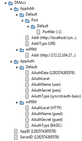
The tree that exists within our example device is represented with the following real DMT sub-tree (the view is extracted from the Managing an OMA DM Device generic DMT browser for an OMA DM v.1.2 enabled device):
| The root node for the OMA DM Accounts object on the device. |
The address settings for an OMA DM server called "Default". | |
Value: "80". | |
Value: "http://localhost/syncml-dm". | |
Value: "URI". | |
The address settings for an OMA DM server called "RM". | |
Value: "http://172.22.104.17/syncml-dm". | |
The collection of OMA DM servers authentication settings. | |
The authentication settings for an OMA DM server called "Default". | |
Varies. | |
Value: <username> for the "Default" OMA DM server. | |
Value: <password> for the "Default" OMA DM server. | |
Value: "syncml:auth-basic". | |
The authentication settings for an OMA DM server called "RM ". | |
Value: "guest" for the "RM" OMA DM server. | |
Value: "guest" for the "RM" OMA DM server. | |
. . . | |
Value: “w7” (defined by the specification). | |
Value: The management session server involved in the current session. |
Having this MO definition for a starting point, we will proceed with designing the control units representing the DM Accounts object.
For each DM account <X>, we'll have a control unit which will unite the account's address properties available in the ./DMAcc/AppAddr/<X> DMT interior node and the account's authentication properties available in ./DMAcc/AppAuth/<X> sub-interior node. All DM account control units for a specific device will share a common parent control unit holding the values of the nodes ./DMAcc/AppID and ./DMAcc/ServerID. Finally, the control units for the DM Account MO along with the other standard MO DevInfo and DevDetail will be united in a folder called Standard Objects. We'll focus on the mapping of DM account CUs to account-specific DMT nodes.
The state variables of the DM account control units are formed taken into account the most important interior nodes and the nodes with important values and the actions – setters of the variables' values. We will also define a constructor action, called "Create DM Account", for creating a DM server account on the device, and a destructor action.
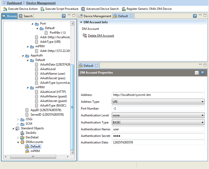
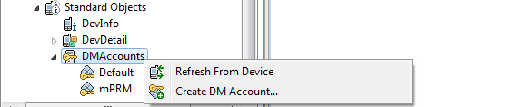
Creating a new DM account in the device's DMT by using a constructor.
DM Account State Variables | DM Account Actions | ||
|---|---|---|---|
Variable Name | Variable ID | Action Name | Action ID |
- | - | Constructor | $create.acc |
- | - | Destructor | $destroy |
Address | Addr | Set Host Address | $set.Addr |
Address Type | AddrType | Set Type of Host Addr | $set.AddrType |
Port Number | PortNbr | Set Server Port | $set.PortNbr |
Authentication Level | AuthLevel | Set Authentication Level | $set.AuthLevel |
Authentication Type | AuthType | Set Auth Type | $set.AuthType |
Authentication Name | AuthName | Set Auth Name | $set.AuthName |
Authentication Secret | AuthSecret | Set Auth Secret | $set.AuthSecret |
Authentication Data | AuthData | Set Auth Data | $set.AuthData |
Create CU Metatype Providers
To describe the structure and format of the control units, designed at the previous step, to RM, we have to provide a metatype for each CU type. CU metatypes describes the CU interface associated with the relevant type including all state variables, actions, parent-child relations, etc. The most convenient way to provide a metatype is by means of XML files, named as <cu_type>.xml within the syncml/cu RM directory. See the user documentation of Generic Device Management RM package for more information about control unit metatypes.
CU metadata XMLs involved in CU-to-DMT mapping should be placed in the syncml/cu directory of RM. The CU metadata XML files for the root "DM Accounts" singleton control unit is syncml/cu/mprm.oma-dm-1.2.std.acc.root.xml and for the DM server account CU type is syncml/cu/mprm.oma-dm-1.2.std.acc.xml.
Creating the metadata XML file of a CU type mapped to a DMT sub-tree involves the following steps:
Create the basic structure of the XML file (we'll look at mprm.oma-dm-1.2.std.acc.xml as it contains more useful and illustrative information):
<metatype-provider><objectclass load="true"><locale>en</locale><name>DM Account</name><id>mprm.oma-dm-1.2.std.acc</id><description>DM Account</description><!—attribute definition --><!—attribute definition -->. . .<!—action definition --><!—action definition -->. . .</objectclass></metatype-provider>The value of the <id> tag must match with the control unit type which will be specified in the corresponding CU-DMTM file within the <cu-type> tag. In our case, the type of the DM account control units is mprm.oma-dm-1.2.std.acc.
pecify parent relation of the control units if any:
The next extract from mprm.oma-dm-1.2.std.acc.xml specifies that all DM account units of an OMA DM device have parent control units of type mprm.oma-dm-1.2.std.acc.root.
<attribute modifier="req"><name>ParentType</name><id>mbs.control.parent.type</id><description>Parent Control Unit types definition</description><type>&string;</type><cardinality>1</cardinality><value><array><scalar>mprm.oma-dm-1.2.std.acc.root</scalar></array></value></attribute>Use the attribute with name "ParentType" and ID "mbs.control.parent.type" to specify a relation with a parent CU type. The actual value of parent control unit must be set within the <value> tag. A control unit type can have more than one parent type, so we must define all parents by using the <array> tag and set the value of <cardinality> tag accordingly.
Specify a super type of the CU type if any (not defined in the mprm.oma-dm-1.2.std.acc.xml).
For the needs of this tutorial, following is an extract taken from another CU metadata XML file, mprm.osgi-meg.device.xml, which shows how to declare super CU types (mprm.generic.osgi.device and mprm.generic.oma-dm.device).
<attribute modifier="req"><name>Super Type</name><id>super</id><description>Super Type</description><type>&string;</type><cardinality>2</cardinality><value><array><scalar>mprm.generic.osgi.device</scalar><scalar>mprm.generic.oma-dm.device</scalar></array></value></attribute>Use the attribute with name "Super Type" and ID "super" to specify a super type relation. Declaring a super type means that a control unit of this type will inherit all state variables and actions from all its super type control units. The super types must be set by using the <value> tag. As a control unit can have more than one super type, we must enclose all super types in an <array> tag and set the value of the <cardinality> tag accordingly.
Describe all state variables of the control units.
The next snippet contains a definition of a state variable with ID Addr and name Address. It will represent the Addr node of the account-specific interior node ./DMAcc/AppAddr/<X>.
<attribute modifier="req"><name>Address</name><id>Addr</id><description>Host address of the SyncML server, IP or URL.</description><type>&string;</type><cardinality>0</cardinality></attribute>Specify all actions of the control units.
The next example contains a definition of an action with ID $set.Addr for setting the value of Addr state variable and thence of the ./DMAcc/AppAddr/<X>/Addr DMT node.
<!-- Set Addr --><objectclass load="true"><locale>en</locale><name>Set host address</name><id>$set.Addr</id><description>Sets host address of the SyncML server, IP or URL.</description><attribute modifier="in"><name>Address</name><id>val</id><description>Thenewserver's address</description><type>&string;</type><cardinality>0</cardinality></attribute></objectclass>Define an action by using the <objectclass> tag. If the content of the <id> tag starts with "$set.". It means that the action is a setter of new values to a certain state variable. The <attribute> tag is used here to define that this action has one input argument (modifier must be set to "in"). The ID of the attribute should match with the data of the relevant <action-definition> within the corresponding CU-DMTM file so that the input argument can be mapped.
Declare constructors
A control unit constructor must have action ID starting with "$create.". In the DM account control unit interface, the constructor is called $create.acc and will be used for adding new DM accounts to the DMT.
<objectclass load="true"><locale>en</locale><name>Create DM Account</name><id>$create.acc</id><description>Creates anewDevice Management account.</description><attribute modifier="in"><name>Account alias</name><id>Name</id><description>The name of thenewaccount</description><type>&string;</type><cardinality>0</cardinality></attribute><attribute modifier="in"><name>Address</name><id>Addr</id><description>Host address of the SyncML server, IP or URL.</description><type>&string;</type><cardinality>0</cardinality></attribute>. . .</objectclass>Declare the destructor
The control unit destructor must have action ID equal to "$destroy".
<objectclass load="true"><locale>en</locale><name>Delete DM Account</name><id>$destroy</id><description>Deletes the DM account.</description></objectclass>
Create Control Unit to DMT Mapping (CU-DMTM)
As previously discussed, CU-DMTM files map specific DMT sub-trees to control units of certain types by using XML syntax.
CU-DMTM files should be placed in the syncml/dmtm directory of RM. The CU-DMTM file for the ./DMAcc MO, discussed in this example, is syncml/dmtm/mprm.generic.oma-dm.device_Acc-1.2.xml.
To create a CU-DMTM XML mapping file, follow the next steps:
Start describing the basic skeleton of the mapping with <control-unit-dmtm> as root tag and specify the type of OMA DM devices this file is applicable for. Use <device-filter> tag described in Control Unit to DMT Mapping to define additional constraints over OMA DM devices.
Here, the mapping is for devices of type
mprm.generic.oma-dm.deviceand the filter narrows the scope of the mapping to devices implementing version 1.2 of the OMA DM specifications.<control-unit-dmtm><device-type>mprm.generic.oma-dm.device</device-type><device-filter>(DmV=1.2)</device-filter><!-- control unit definition --><!-- control unit definition -->. . .</control-unit-dmtm>Start defining a control unit type related to a DMT node of interest by opening a <control-unit> tag.
<control-unit><!— DMT node scope definition --><!— CU type mapping --><!— CU ID mapping --><!— CU parent mapping --><!— CU parent mapping -->. . .<!— CU state variable mapping --><!— CU state variable mapping -->. . .<!— CU action mapping --><!— CU action mapping -->. . .</control-unit>Specify the scope of the control units of the relevant type in the DMT, i.e. one or more DMT nodes which are considered as roots of the DMT sub-trees. Use the <dmt-node> tag as described in Control Unit to DMT Mapping.
The snippet shows that the currently defined control unit type is scoped to the ./DMAcc/AppAddr/<X> nodes.
<dmt-node><path-patterntry-struct="true">./DMAcc/AppAddr/{X}</path-pattern></dmt-node>Every other node URIs used in the definition of this control unit type might be relative to the node(s) specified by this element. The {X} variable is resolved at runtime against a particular device. The resolving procedure will determine all DMT nodes that match the pattern, which in turn will determine the number of control unit instances that will be available of this type. ./DMAcc/AppAddr/{X} must be a valid node of target device's DMT.
Declare the type of the control units associated with the DMT node within a <cu-type> tag as described above. The type must match with the type ID specified in the corresponding CU metadata XML file.
The extract from the DM account CU-DMTM file specifies that the control unit type being mapped is
mprm.oma-dm-1.2.std.accwhose structure has been discussed in the previous section.<cu-type>mprm.oma-dm-1.2.std.acc</cu-type>Declare the ID of current control unit within a <cu-id> tag.
<cu-id><id-format>{X}</id-format></cu-id>In case the ID format contains a variable, the IDs are determined at runtime by substituting the variables (e.g. {X}) with their values according to the URI pattern within the relevant <dmt-node> tag.
Declare the parent type(s) if the control units have parents within one or more <cu-parent> tag.
<cu-parent><cu-type>mprm.oma-dm-1.2.std.acc.root</cu-type><cu-id><id-format>DMAccounts</id-format></cu-id></cu-parent>The parent type and ID should be available in a CU metadata XML file. In the example, the DM account control units will have a common parent of type mprm.oma-dm-1.2.std.acc.root, previously discussed, and with ID equal to "DMAccounts". The CU metadata XML file for mprm.oma-dm-1.2.std.acc.root is syncml/cu/mprm.oma-dm-1.2.std.acc.root.xml.
Map all control unit state variables to specific DMT nodes. Use <state-var> tags.
<!-- AppAddr subtree --><state-var><state-var-id>Addr</state-var-id><node-attr attr-name="value">Addr</node-attr></state-var>The Addr node specified in the extract is relative to the DMT URI specified in the <dmt-node> tag of the current control unit definition, i.e. its URI is ./DMAcc/AppAddr/{X}/Addr. The Addr node must be a valid node of DMT of the target device. There must be a corresponding CU metadata file (in our case syncml/cu/mprm.oma-dm-1.2.std.acc.xml), which contains a state variable definition with ID equal to the content of the <state-var-id> tag.
<!-- Address part --><attribute modifier="req"><name>Address</name><id>Addr</id><description>Host address of the SyncML server, IP or URL.</description><type>&string;</type><cardinality>0</cardinality></attribute>Map all control unit actions to DM commands over a specific DMT node. Use <action> tags.
Setter action definition - Setter actions are expected to have ID $set.<state_var_id>.
<!-- Set Address --><action><action-id>$set.Addr</action-id><action-definition><Replace><Item><Target><LocURI>Addr</LocURI></Target><Meta><Format xmlns='syncml:metinf'>chr</Format></Meta><Data>{val}</Data></Item></Replace></action-definition><refresh><cu-state><this/></cu-state></refresh></action>The action's input argument defined as {val} will be used to replace the Addr node of device's DMT. The URI of the node is ./DMAcc/AppAddr/{X}/Addr where {X} is resolved at runtime and will be mapped to a concrete DM server account.
There must be a corresponding CU metadata file where an action with the same ID and input argument ID are defined.
<!-- Set Addr --><objectclass load="true"><locale>en</locale><name>Set host address</name><id>$set.Addr</id><description>Sets host address of the SyncML server, IP or URL.</description><attribute modifier="in"><name>Address</name><id>val</id><description>Thenewserver's address</description><type>&string;</type><cardinality>0</cardinality></attribute></objectclass>Execute action definition
<action><action-id>start</action-id><action-definition><Exec><Item><Target><LocURI>{$multi:$}/RM/Bundles/{bundle_id}/Operations/Start</LocURI></Target></Item></Exec></action-definition><refresh><cu-instance><cu-type>meg.deployment.package</cu-type></cu-instance><cu-instance><cu-type>meg.deployment.package.bundle</cu-type></cu-instance></refresh></action>The action definition taken from the syncml/dmtm/mprm.osgi-meg.device_Deployment.xml specifies that invoking the start control unit action will result in executing the OMA DM "Exec" operation over a specific node of the DMT of the target device. {bundle_id} is resolved at runtime according to the concrete CU definition. The <refresh> tag is used to indicate that RM has to refresh the state of all control unit instances of the defined type on the backend after the start action is complete.
External action definition
<action><action-id>update</action-id><external/><refresh><cu-instance><cu-type>meg.deployment.package</cu-type></cu-instance><cu-instance><cu-type>meg.deployment.package.bundle</cu-type></cu-instance></refresh></action>Such an external action must be implemented and registered in the MS OSGi framework as a
com.prosyst.syncml.dm.manager.map.Actionservice for the defined control unit type and action ID. By specifying some action as "external", a programmer gains more flexibility while implementing the specific action.
Define control unit constructors as CU actions starting with $create..
The next example maps the constructor $create.acc to an "Add" OMA DM operation which has target DMT node ./DMAcc/AppAddr/<Name>.
<action><action-id>$create.acc</action-id><action-definition><!-- Add Root node and the display name --><Add><Item><Target><LocURI>./DMAcc/AppAddr/{Name}</LocURI></Target><Meta><Format xmlns='syncml:metinf'>node</Format></Meta></Item></Add>. . .</action-definition><refresh><cu-instance><cu-type>mprm.oma-dm-1.2.std.acc</cu-type></cu-instance></refresh></action>Define the control destructor as a CU action whose ID is equal to $destroy.
<!-- Destructor --><action><action-id>$destroy</action-id><action-definition><Delete><Item><Target><LocURI>./DMAcc/AppAddr/{X}</LocURI></Target></Item><Item><Target><LocURI>./DMAcc/AppAuth/{X}</LocURI></Target></Item></Delete></action-definition><refresh><cu-instance><cu-type>mprm.oma-dm-1.2.std.acc</cu-type></cu-instance></refresh></action>