Goals of the Control Unit Abstraction
The control unit abstraction aims to unify the control of miscellaneous device units. It introduces a common interface to manage different types of device controllable modules - these can be software components, configurations, user settings, etc.
Structure of a Control Unit
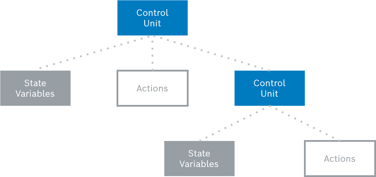
The structure that a control unit can have is illustrated bellow:
State Variables and Actions
A control unit is a collection of state variables and actions. State variables represent control unit's specific parameters, for example an X10 lamp may have a state variable for indicating on and off, and have unique ID within the control unit scope and value of certain type. You can only get a state variable's value by making a query. Direct modification with a new value is not supported. If the state variable's value can be changed from outside, the control unit should have an action for such an operation.
The actions of a control unit are the commands that the control unit can execute, such as turning a lamp on and off. An action has ID, unique within the control unit scope, and may have input and/or output arguments.
Control Unit State and Interface
The collection of state variable IDs and types and of action IDs form the interface of the control unit. The current values of control unit's state variables determine the present state of the control unit.
The control unit abstraction provides a unified, well-known way to monitor the state of and execute an action on a control unit resulting in a state change. Therefore, although there is a great flexibility in what tasks can be invoked on units and the state variables they provide, applications can manage control units in a uniform way, without the need to have specific knowledge about the underlying resources.
Control Unit Type and ID
Each control unit instance has associated type and ID. The control unit's type identifies its interface. It is possible to have many control unit instances of the same type, sharing the same set of state variables and action identifiers, but which are in different states. The control unit ID has to be unique in the scope of the corresponding type for a particular device.
Version of the Control Unit Type
The interface of control units of a specific type may evolve between its successive implementations - for example, the newer version of the implementation may add some new state variables and actions. To support this scenario, the control unit type may be supplemented with version. This allows additional attributes and actions to be added without the need of introducing a new type. Newer versions of a given type should be backward compatible with the older ones. In this way an older management application will still be able to work with the new type version, taking benefit only from type's older features, while newer applications will be able to take advantage of the new features provided by the extended type.
Control Unit Metatypes
In order to use a specific control unit, an application has to know its interface. In general, there are two ways to deliver this knowledge:
The application has been specifically designed to work with control units of a given type and version and it queries state variables and invokes actions in a way hard-coded into the application.
The application dynamically gets information about state variables and actions supported by control units of a given type and by using this information it checks their state and invokes their actions.
The description of a control unit interface is called control unit metatype and is supplied by a Metatype Provider. Control unit metatyping relies on the Bosch Digital Metatype support which in turn is based on the OSGi Metatype Specification. For details on the format and definition of control unit metadata, see the Control Unit Metatyping Developer Guide.
Control Unit Hierarchies
You can build a nested structure of control units, convenient for logical grouping of units and especially useful for representing more complex resources - configurations, hardware and software systems, which may be decomposed to a hierarchy of sub-components, achieving an arbitrary level of granularity. For example, a control unit hierarchy may be defined to represent a user group with dynamic list of member users.
Control Unit Inheritance
A control unit type can extend a super control unit type, meaning that it inherits all state variables and actions of its superior.
Predefined Actions
A control unit type can have several categories of predefined actions related to special "factory" functionality:
Constructors - Explicitly create a control unit instance. They can be recognized by action ID, which should start with "$create.".
Destructor - Explicitly destroy a control unit instance and have action ID starting with "$destroy". A control unit type can have only one destructor.
Finders - Filter control units of a specific type by certain criteria. Finder action IDs are prefixed with "$find.".
Device Management Tree
The potentially large numbers of devices as well as their different logical or physical properties imply that management of devices network would be much easier if they could be grouped into a tree-like directory structure. By using the management tree, devices could be hierarchically organized by various criteria - location, organization group, etc. This tree-like mechanism brings the following advantages:
You can define management tasks over a whole set of devices that are forming a separate branch of the tree.
You can locate a particular device much easier.
You can view only the nodes you are interested in, if you are an operator.
Basically, the RM management tree contains two kinds of nodes:
Device group nodes – These nodes are considered as directories for devices and descendant device groups.
Device nodes – They are always leaf nodes and represent the managed devices. A device node contains the control units associated with the device the node represents.
Nodes can have specific configurable settings, which can be inherited by their sub-groups and devices. Therefore, you can configure a whole branch of devices with a single operation.
Representation of a Device Managed in RM
In the multi-device environment of RM, control units are associated with a specific device host, which appears as a managed object in the device management tree. Regarding control units, a managed device can be the source of a hierarchy of control units (device root and component), which provide access to various manageable resource on the device.
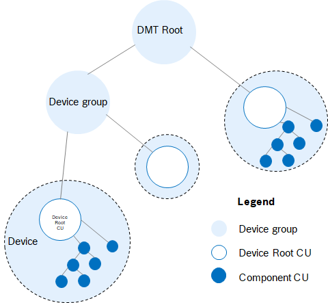
Each device managed by RM is represented as hierarchical set of control units with a single control unit standing as the root of the hierarchy and zero or more child control units, which in turn can have child control units. The root control unit of the device hierarchy is called device root control unit and its child control units - component control units.
The device root control unit acts as the actual representation of the device in RM, while component control units represent different sub-components and resources on that target device, which are subject to management.
Device root control units are treated as main units for administration through RM. They enter the management tree as device nodes.
Component control units are considered to represent device components and resources. All component control units belong to a particular device (represented as a device root control unit). Component control units have meaning and uniqueness only in the scope of their device root. They are not considered as part of the management tree, as they are part of a managed device in the tree. Component control units may provide hierarchy relations between each other in the scope of their device root.
To summarize, a device is represented as a hierarchy of control units. The device root control unit is the main unit that exists as a node in the management tree, and the device's components form a hierarchical structure, as shown in the next figure:
Device Identification
Each device managed by the RM is uniquely identified by device type and device ID. The type denotes a class of devices having the similar characteristics, while the ID identifies a particular device of a given type. The device ID must be unique in the scope of a particular device type.
The device type and ID are equivalent to the type and ID of the corresponding device root control unit (see "Control Unit Identification" section below).
Control Unit Types and Versions
Control unit types must strictly define either device root control units or component control units. It is not allowed control units of a given type to act simultaneously as device roots and as components.
Device root control unit types may have only one version provided in RM. Component control units may have more than one version provided in RM, but only one version in the scope of a particular device root. This allows for parallel definition and use of component control units of the same type but with differences in their interfaces.
For a component control unit type, RM also stores all versions of the control unit metatype and indicates the version a concrete device root runs.
Control Unit Identification
To completely identify device roots and components, RM uses the following set of attributes:
Control unit type – Type of the control unit
Control unit ID – ID of the control unit
Device type – Type of the device this component belongs to
Device ID – ID of the device this component belongs to
As device root control units are fully identified in RM with their type and ID, type and ID have the same value as, respectively, device type and device ID.
Differences in the Treatment of Device Roots and Components
Device root control units are considered as the main management targets:
Only device root control units are involved in management tasks (even though it is possible that an operation targets a device's components).
Pending management tasks are bound to device roots as well.
The mechanisms for distribution of control unit management over clustered management servers again concerns device roots only – the components are not addressed separately.
Device root control unit instances shall combine two types of information data – control unit information and node information. Control unit information refers to the control unit state - the set of its state variables along with their values. Node information refers to attributes of the node in the management tree – node path, parent path, node properties, etc. Component control units contain only control unit information.
Device root control units have no hierarchy relations with other control units, while components may define relations in the scope of their device.
Finders cannot be defined for device root control units – RM offers its own mechanism for device search within its device management tree.
Components may be provided with more than one version of a specific type in RM, while there must be exactly one version provided for a specific device type.
Components are uniquely identified only in the scope of their device, while device roots are uniquely identified in RM with their type and ID.
Constructors and destructors have the following meaning:
For component control units – creating and destroying resources
For device root control units – registering and unregistering devices with RM
Relations of Control Unit Types
Device-Component Relations
The system provides a strict mechanism for declaring the relations between device and component control unit types. That is, at any moment it is well defined which component types belong to a particular device type and vice versa - which are the device types to which a component type belongs.
As concluded, a component type is allowed to belong to more that one device type.
Providing of those declarations is based on declaration by each component type to which device-types it belongs. Therefore, a device representation could be pluggably extended simply by registering new component types, which declare belonging to an existing device-type. The device-type provider itself does not need to know the set of component types belonging to its device type.
Parent-Sub Hierarchy Relations of Component CUs
As already mentioned, component control units may form hierarchies in the scope of a particular device representation. These hierarchies are based on parent-sub control unit relations among the component types. Declaration of those relations is based on declaring parent types by each component type. Therefore, existing hierarchies could be pluggably extended by simply adding a new component type that declares an existing type as its parent. The system itself provides well-defined means for monitoring such relations, i.e. at any moment it is known which are the subtypes of a given parent type and vice versa – which are the parent types of a given subtype.
Type Inheritance Relations
Inheritance Rules
The system allows multiple extending of control unit types, that is, a control unit type can extend one or more control unit types.
Component types cannot extend device types and vice versa.
Control Unit Type Inheritance Support
Monitoring inheritance:
Metatype aggregation – Since extending a control unit type means inheriting all actions and state variables, the system provides metatype aggregation of the extending types by uniting the declared metatypes of the extending type itself and its super types.
Super-extension relations monitor – The system provides well-defined means for administration monitor on the super-extending type relations. At any moment it is known the extending types of a super one, and the super types of an extending one.
Constructing parent-sub relations of component types regarding the super-extension relations as follows:
Sub types of a component type are determined as the set of all declared sub types (i.e. all types that declare the type as parent) united with all extensions of the declared sub types.
Parent types of a component type are determined as the set of all declared parent types of the type united with the declared parent types for all ancestors (super types) of the given type.
Constructing device-component relations regarding the super-extension relations as follows:
Component types of a device type are determined as the set of all declared component types (i.e. all component types that declare the type as belonging device type) united with the declared component types for all ancestors (super types) of the device type.
Device types of a component type are determined as the set of all declared device types united with all extensions of the declared device types.
Listing control units:
Listing control units of a specific type lists also the control units of all extending types.
Mass Tasks on a particular control unit type include the control unit instances of its extending types as well.
Device Capabilities
Overview
The concept of device capabilities is defined in JSR 124, "J2EE Client Provisioning". In general, device capabilities are key-value pairs representing certain features and characteristics that a device has, for example the available free memory on the device. In RM, capabilities indicate the ability of the device to execute particular applications, and are used to determine the correct client bundle when installing an application from the Software Repository. The capabilities of the target device are matched against the requirements of each variant (i.e. client bundle) of the application being installed.
RM provides extra flexibility in the matching mechanism between device capabilities and application requirements by means of platform properties, featuring capabilities and requirements with the same name. Platform properties have unique key and one or more values. They can also have additional relations among each other, therefore they could be matched in the most suitable way. The default properties saved in RM are defined in JSR 124. Custom platform properties can be defined as well to enhance the resolving of application requirements.
Refer to the Software Repository documentation for more information about the role of device capabilities.
There are three ways to define device capabilities:
In a programming way – By implementing a plugin exporting frequently changing device capabilities to the system. See Developer Guide for more information about a developing a capability provider.
By using the console – By specifying explicitly device capabilities for a selected device through a visual interface. See User Guide for more information.
Pre-defined capabilities – By defining static capabilities for a device type in an XML file. This approach is explained in the next paragraphs.
Static Capabilities Definition
The static capabilities are defined in the devices.xml located in the device_conf directory of the RM installation. You can add your own capability definitions obeying the relevant Document Type Definition (DTD). The DTD, sc.dtd, is also available in the device_conf folder.
Basically, the capability XML file has the following structure:
<devices> – The root element containing nested device capability definitions.
<device> – The capability descriptions of a device type. The element must contain a type identifier, zero or more capabilities, zero or more conditions based on device root state variables and zero or more conditions based on component state variables.
<identifier> – The device type. The value of this element is set as the HardwarePlatform.DeviceIdentifier capability for the devices of this type.
<capability> – A static capability which will be set if the device satisfies the specified conditions.
· <capability-name> – The capability name.
· <capability-value> – The values of the capability, separated with commas.
<device-mapping> – A list of device root state conditions for filtering the devices which will acquire the defined capabilities. Each condition contains matching Rules (<match-all>, <match-not>, <match-any>) against state variable values (<request-mapping>).
· <request-mapping> – A matching constraint on a state variable value. Can be placed within a matching rule element.
· <header-name> – The state variable ID.
· <header-value> – The state variable value. Can be specified as:
· xxx – Equivalent to "is equal to xxx".
· xxx* – Equivalent to "starts with xxx".
· *xxx* – Equivalent to "contains xxx".
· *xxx – Equivalent to "ends with xxx".
· <match-all>, <match-any>, <match-not> – Matching Rules. Can be nested in each other and can surround a <request-mapping>.
<component-mapping> – A list of component state conditions for filtering the devices which will acquire the defined capabilities. Each condition contains matching Rules (<match-all>, <match-not>, <match-any>) against state variable values (<request-mapping>) of a specific component control unit type (<component-type>).
· <component-type> – The component type whose state variables shape the capabilities conditions.
· <request-mapping> – The same as in <device-mapping>.
· <match-all>, <match-any>, <match-not> – The same as in <device-mapping>.
The following example device capability XML definition states that OSGi-enabled devices (of type "mprm.osgi.device"), which are:
Online
Connected to RM over the TCP Transport Service
Do not have address starting with 132.22.25
And have the following components:
OSGi bundles with ID starting with 1 and location starting with "../../"
A configuration dictionary "
mbs.devicem.pid"
will receive capabilities capability_name1 with value capability_value1 and capability_name2 with value capability_value2.
An example device capability XML is presented below:
<?xml version="1.0" encoding="UTF-8"?> <devices> <device> <identifier>mprm.osgi.device</identifier> <capability> <capability-name>capability_name1</capability-name> <capability-value>capability_value1</capability-value> </capability> <capability> <capability-name>capability_name2</capability-name> <capability-value>capability_value2</capability-value> </capability> <device-mapping> <match-all> <request-mapping> <header-name>status</header-name> <header-value>Online</header-value> </request-mapping> <request-mapping> <header-name>transport</header-name> <header-value>tcp</header-value> </request-mapping> <match-not> <request-mapping> <header-name>host</header-name> <header-value>132.22.25.*</header-value> </request-mapping> </match-not> </match-all> </device-mapping> <component-mapping> <component-type>BUNDLE</component-type> <match-all> <request-mapping> <header-name>id</header-name> <header-value>1*</header-value> </request-mapping> <request-mapping> <header-name>location</header-name> <header-value>../../*</header-value> </request-mapping> </match-all> </component-mapping> <component-mapping> <component-type>CONFIGURATION</component-type> <request-mapping> <header-name>pid</header-name> <header-value>mbs.devicem.pid</header-value> </request-mapping> </component-mapping> </device> </devices>