Step 4 - Remote control
You can use the Bosch IoT Suite UI to send messages to your Arduino device and change the values of its features.
In this context, the message is a one-off command that is executed instantly on an individual device, and in particular on one of its features.
In the future, when you have provisioned multiple devices, you can include them in mass management campaigns to make these executions automated and recurrent.
For more details, see Mass management tasks and Mass management rules.
Set a specific color to one of the LEDs
Your Arduino board has 5 LEDs which can be controlled remotely via API and thus also via the UI.
Let's change the color of the first LED by sending a message to the board's leds feature.
For that purpose:
Navigate to Devices from the left sidebar.
Select your Arduino device.
Select Message.
In the message Subject field, enter a command supported by this feature, as defined in its Vorto model
(org.eclipse.ditto.examples.arduino.carrier:LEDs:1.0.0).
In our example, the command will be setPixelColor. This command sets the color of the indexed LED.The index value corresponds to the LED's position on the Opla Kit.
In the Type field, select JSON.
In the Message field, add the message payload.
As you have selected the JSON format, write a suitable JSON as defined in the Vorto model:
setPixelColor(index as int "Pixel index", color as Color).Let's set the first LED's color to blue by sending the following payload:
{"index":0,"color": {"r":0,"g":0,"b":100}}Enter a Timeout, e.g. 10 seconds.
As Direction select To the thing (feature).
As Receiver/Sender select Feature which will open the feature list on the right.
Select the leds feature.
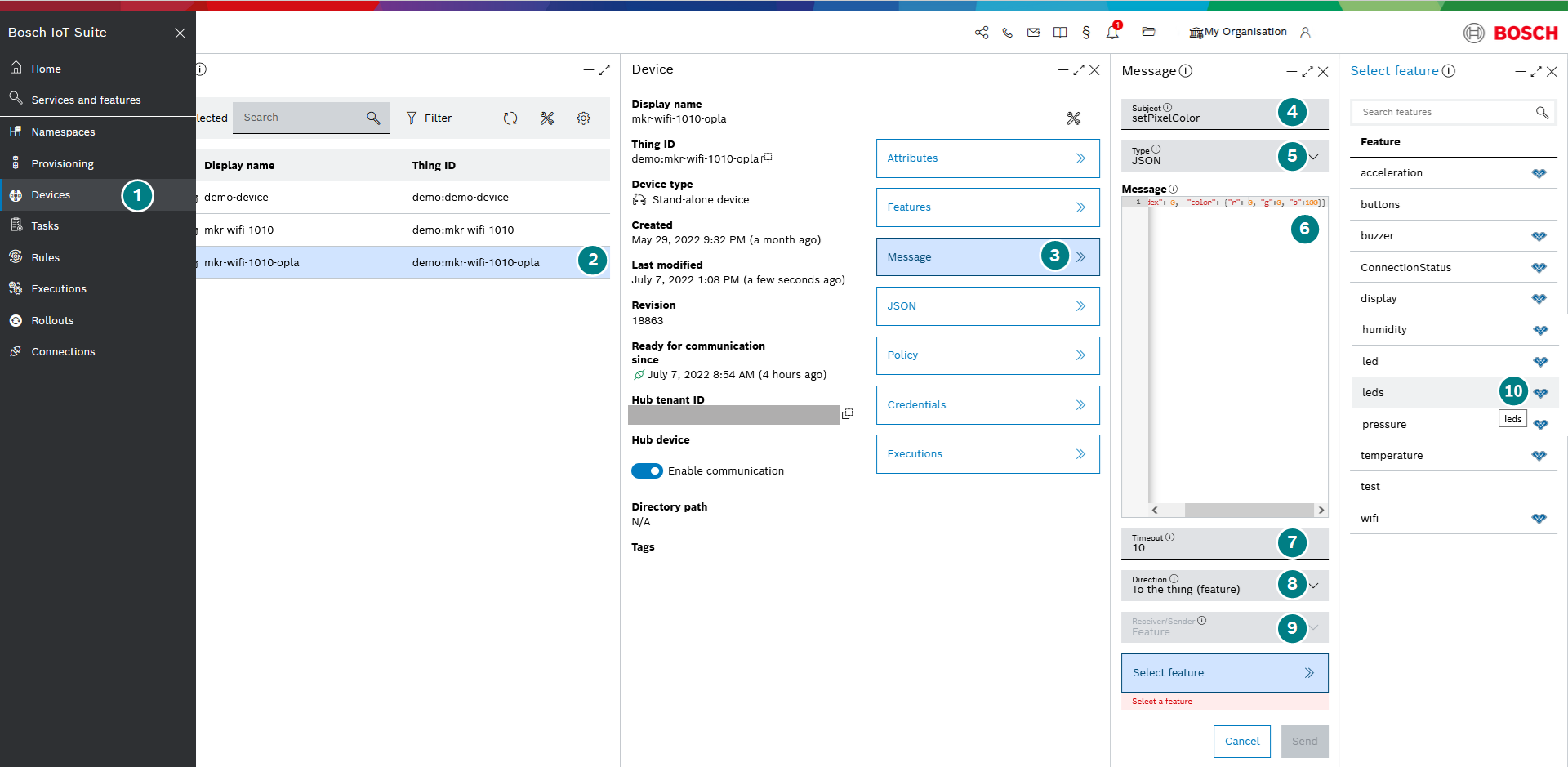
Click Send to submit the message.
Your message will be sent to the physical device where the firmware consumes your message-related data and changes the color of the LED.
In scenarios where you want to remotely control an IoT asset, it is important to check whether the device is connected and listening at all.
Upon successful execution, you will receive a 200 status code and the first LED on the Arduino board will be lit in bright blue color.

Lower the brightness of the blue LED
Let's change the brightness of the LED that we just lit in blue by sending one more message to the leds feature.
The process is the same as described above, but this time:
Enter setBrightness in the Subject field.
In the Type field, select Text. With that you will send the custom payload directly as a value.
In the Message field, add the message payload.
As you have selected the text format, just write a suitable int in the range defined in the Vorto model (<MIN 0, MAX 255>), e.g. 10.

Once the message has been successfully sent, you can verify the change.
If you do not have the board in front of you, you can also verify your work by checking the values reported by the specific feature back to the cloud service, as the UI displays the latest values.
Open the Features blade and check whether the brightness value of the leds feature has been updated.
